

Closed-Loop Controlled Car
Overview

The goal of this project was to design a system capable of transporting a 12-inch long, 1-inch thick vertical bar a variable distance of 5–10 feet and back without allowing it to topple. The bar was placed on a horizontal platform and supported only on its bottom face, with no glues or fasteners used to secure it.
To accomplish this, the team designed, constructed, and tested a miniature car capable of carrying a 12-inch aluminum extrusion 10 feet and returning in the shortest possible time while maintaining stability. The system utilized a DC motor, Arduino microcontroller, and motor driver to control the vehicle’s motion. The project was completed collaboratively in a team of four, focusing on stability, control, and efficient transport.
Full Car Model
Multi-Body Dynamic Model
The team performed a Tipping Acceleration Analysis to determine the maximum theoretical acceleration the system can withstand with the bar through 1D Kinematics. The value determined was around 32.174 in/s^2.
To determine the velocity profile of the car, a simplified version of the motion was analyzed using SolidWorks Motion. For a 12-inch long bar with a 1 in × 1 in base, the maximum allowable acceleration before the bar tips was calculated using 𝑔𝑤/𝐿, where 𝐿 = 12 inches and w = 1 inch. This results in a maximum acceleration of 32.174 in/s² was verified through SolidWorks Motion Study.
In SolidWorks, an assembly was created consisting of a 120-inch track, a 6-inch long plate, and a 1 × 1 × 12-inch extrusion. The extrusion was positioned at the center of the plate, while the plate was aligned with the end of the track. The plate travels 120 inches (10 feet) when its front edge reaches the same plane as the end of the track. The assembly was constrained so that the plate has only one degree of freedom, moving along the track, and all mates were defined to avoid redundancy.
_edited.png)
Simplified Car Motion CAD
Simulation Graph Models

Max Acceleration Profile Graph

To verify the critical acceleration, a reaction force sensor was applied at the front of the bar. When the bar begins to tip, the reaction force at this point drops to zero because the weight shifts entirely to the back edge of the bar. A linear motor was applied to the car with gradually increasing acceleration, and two plots were generated: car acceleration vs. time and the bar’s reaction force vs. time. At approximately 2 seconds, the reaction force approaches 0 lbf, indicating the onset of tipping, while the corresponding acceleration is about 32 in/s². This confirms the predicted critical acceleration for the system.
Reaction Force Profile Graph
After determining the critical acceleration, I created a velocity profile for the car’s motion across the track, shown in the graph to the right. The profile was designed while considering the maximum allowable acceleration, minimizing sudden jerks, and ensuring that the motion could be easily implemented in code. From the graph, the car accelerates linearly from 0 to about 60 in/s over the first 2 seconds, then decelerates linearly until the velocity reaches about −60 in/s at around 6 seconds, before accelerating again back to 0 in/s at about 7.8 seconds.
This motion corresponds to an acceleration of approximately ±31.54 in/s², which is slightly below the critical acceleration of the system to provide a safety margin if the car momentarily exceeds the predicted value. The piecewise linear shape of the velocity profile also simplifies implementation in code. According to the SolidWorks Motion simulation, the full motion takes approximately 7.8 seconds.
However, this simulation assumes ideal conditions. In practice, factors such as a slightly uneven floor or bar surface, misalignment of the car platform, or small bumps in the wheels or track may introduce additional disturbances that could affect the motion. The Motion Simulation is shown to the right.
Simulation Graph Models
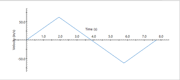
Velocity Profile Graph
Motion Simulation
Car Motion Video
As a team, we determined the car platform and the placement of the Arduino Uno, L298N dual H-Bridge motor driver, and DC motor, with all CAD models created in SolidWorks. The Arduino Uno acts as the control unit, sending signals to the L298N driver, which regulates the motor’s power and direction. The motor shaft is connected to a coupler that transfers rotational motion through a rubber belt to a secondary coupler attached to the wheel axle, allowing the motor to drive the wheels.
The team aimed to keep the platform compact while leaving space in the center for the extruded bar.

Top View

Front View

Side View
.png)
Car Model CAD
The final design uses a 5 in × 7 in × 0.25 in MDF platform, with the Arduino, motor driver, and DC motor mounted securely on top using tapped holes. The layout ensures that all electronic components remain accessible and that wiring can be connected without interfering with the bar or the wheels. To maintain this clearance, four laser-cut wheel brackets were designed to hold the wheel shafts, creating enough space for the bar to move freely without contacting any components during operation. Most structural parts of the system were either laser cut or 3D printed.
The car also includes 3D-printed wheel mounts and wheels. The mounts are attached at each corner of the platform and support the wheel axle shafts. The wheels are superglued to the axle, and each wheel includes a rubber O-ring to increase traction on uneven surfaces. The CAD model shows a simplified representation of the wheel design.
Final Product Testing
The performance evaluation of our project was divided into two parts: the baseline test and the competition. In the baseline test, the car was required to travel 10 ft forward and return without causing the bar to tip over. After successfully completing this requirement, the project moved on to the competition phase, where each group attempted to travel 6 ft forward and back in the shortest possible time. The recorded video is shown below.
Final Model Testing
Car Model Testing Video