

SolidWorks Motion Series
01
Four Bar Linkage
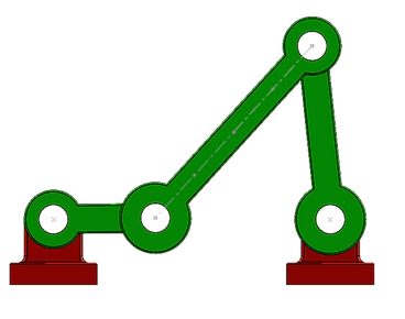
4 Bar Linkage Model
System Analysis
In the motion analysis, the crank rotates at 20 RPM for approximately 9 seconds, completing three full revolutions. During this time, the paths of three selected points on the coupler are traced. These coupler curves reflect a combination of translational and rotational motion, producing intricate looping trajectories. Meanwhile, the rocker moves back and forth in an oscillatory manner. Overall, the project illustrates how a single degree of freedom—the rotation of the crank—can generate controlled oscillatory motion within the mechanism.
.png)
A four-bar linkage is a basic mechanical mechanism consisting of four rigid links connected by four revolute (pinned) joints, which allow the links to rotate relative to one another. One of these joints is fixed to the ground and acts as the stationary reference frame. The crank, or input link, provides motion to the system through rotation. The rocker, or output link, moves in response to the crank, typically oscillating or rotating. The coupler link connects the crank and rocker, transmitting motion between them.
For the ME360 project shown on the left, the crank is the leftmost link and the rocker is the rightmost link. The model and motion analysis were created using SolidWorks and SolidWorks Motion.
4 Bar Motion Analysis
4 Bar Linkage Motion Video
On the left represents traced motion paths of three points located at ¼, ½, and ¾ along the Extension to visualize how different sections move during operation. These paths were actuated by a rotatory motor. Utilizing the Results and Plots tool in the Motion Study, we selected Trace Path under the Displacement/Velocity/Acceleration category and generated the paths for each point. This allowed us to compare their trajectories and better understand how motion varies along the length of the Extension.
Coupler Traced Paths
Velocity Profiles
The velocity of the midpoint of the extension link was traced in the X (horizontal) and Y (vertical) directions during the motion study. The X-velocity profile shows the horizontal motion of the midpoint as the crank rotates, while the Y-velocity profile shows the vertical motion of the same point. Because the mechanism is a four-bar linkage, the midpoint undergoes both translation and rotation, producing periodic velocity variations in both directions.
From the plots, the maximum X-velocity is approximately 6 in/s, while the maximum Y-velocity is approximately 4 in/s. The repeating patterns indicate the cyclic motion of the mechanism as the crank completes each rotation.

X-Velocity Plot

Y-Velocity Plot
Motor Profiles
With the same mechanism, the material of all four-bar components was changed to Plain Carbon Steel to model a more realistic mass and inertia. Gravity was then enabled in the Motion Study to account for the weight of each link during motion. After recalculating the simulation, the motor torque vs. time plot was generated to capture how much torque the motor must supply throughout each cycle. The torque is not constant because the linkage’s geometry and gravitational moment change as the crank rotates, causing the load on the motor to rise and fall periodically. From the plot, the maximum motor torque is approximately 0.16 lbf·in, occurring at a repeatable point in each cycle.

Plain Carbon Steel Material
The maximum motor torque (~0.16 lbf·in) occurs when the crank angle is approximately −36° (or 324°). From the plots, this peak torque occurs repeatedly at about 2.7 s, 5.7 s, and 8.7 s, showing a periodic pattern of roughly every 3 seconds as the mechanism completes each cycle.

Motor Torque Plot
The plot below shows the angular displacement of the crank over time during the motion study. The crank rotates at a constant angular speed, resulting in a linear increase in angle with time. When the crank completes a full rotation, the angle resets from +178° to −178°, creating the repeating sawtooth pattern observed in the graph. The maximum crank angle reached is approximately 178°, indicating the point just before the crank completes a full revolution and the angle measurement resets for the next cycle.

Crank Angle Plot
Reaction Forces/Power
The reaction forces at the two ground bearings were plotted during the motion study after assigning Plain Carbon Steel material properties and enabling gravity. The first plot shows the reaction force at the bearing connected to the crank, while the second plot shows the reaction force at the new bearing connected to the rocker.
For the crank bearing, the reaction force varies periodically as the crank rotates and the linkage transmits forces through the mechanism. From the plot, the maximum reaction force is approximately 3.0 lbf, while the minimum force is about 1.7 lbf. These variations occur because the orientation of the links and the gravitational loads change throughout each cycle.
For the rocker bearing (NewBearing), the reaction force also varies periodically due to the oscillating motion of the rocker link. The maximum reaction force is approximately 2.3 lbf, while the minimum force is about 1.3 lbf. The repeating pattern in both plots reflects the cyclic loading experienced by the bearings as the four-bar linkage completes each rotation of the crank.

Bearing w/Crank

New Bearing w/Rocker
The motor power plot shows how the power required to drive the mechanism changes over time while the crank rotates at a constant angular speed. Even though the speed remains constant, the required power varies because the geometry of the linkage changes, the moment arm of gravity shifts, and the links accelerate and decelerate throughout the cycle.
The plot shows positive peaks of approximately 1.3 W, where the motor supplies energy to drive the mechanism, and negative values around −1.4 W, where the mechanism returns energy to the motor as gravity assists the motion. The repeating pattern reflects the periodic behavior of the four-bar linkage as the crank completes each rotation.

Motor Power Consumption
Negative motor torque values occur when the mechanism itself assists the motor’s motion instead of resisting it. This happens when the weight and inertia of the links cause them to move in the same direction as the crank rotation, effectively pushing the motor rather than requiring it to drive the system. In these portions of the cycle, gravity and the motion of the connected links transfer energy back to the motor, resulting in a negative torque value. This behavior reflects the dynamic interaction between the rotating crank and the moving links of the four-bar mechanism as their positions and moment arms change throughout the cycle.
02
Mechanism Synthesis
This project focuses on mechanism synthesis, where the goal is to design mechanical linkages that produce a specific motion. The objective is to determine the lengths of the links and the locations of pivot points so that a mechanism can move an object between desired positions. These exercises help demonstrate how linkages can generate controlled motion patterns and are commonly used in electromechanical systems and mechanical design.
.png)
Mechanism Synthesis
1 DOF Mechanism
.png)
Planar Mechanism Example
These diagrams illustrate the geometric and mathematical setup used to design and analyze a planar linkage mechanism with one degree of freedom (1 DOF). The joints labeled A–G represent pivot points connected by rigid links with defined lengths, which determine how the mechanism moves. By specifying link lengths and input angles, the motion of the entire system can be simulated and adjusted to study different configurations. Using the Grubler criterion, the mechanism is verified to have a single degree of freedom, meaning one input rotation controls the motion of all other links.
These illustrations below help visualize how linkages are designed and manipulated to explore different mechanical motions and determine whether the system behaves as a mechanism rather than a rigid structure.

Configuration 1

Configuration 2
Slider Crank Mechanism

Slider Crank System
These diagrams illustrate the design and geometric analysis of a crank–slider mechanism, a common example of a 1-degree-of-freedom (1 DOF) linkage. In this mechanism, the crank rotates continuously, driving a connecting link that converts rotational motion into the linear motion of a slider. The top image shows the conceptual mechanism, where the crank completes a full revolution while point B follows a circular path and point C moves along a constrained linear path inside the guide. The lower diagram represents the geometric construction used to determine link lengths, angles, and positions during the design process. By defining distances between points and input angles, the motion of the mechanism can be predicted and adjusted to achieve the desired movement. This analysis helps ensure that the linkage produces smooth motion while satisfying the required mechanical constraints.

Math Illustration Slider Rocker Motion
Two Position Synthesis

Math Illustration Simulation
The blue bar represents a rigid body that must move between two specified positions: an initial horizontal position and a final position rotated 45°. The center points of the bar are separated by 40 inches, while the bar itself has a length of 30 inches. These constraints define the geometric conditions that the linkage mechanism must satisfy so that the bar can move smoothly between the two orientations.

Position Synthesis Example
The points A and B represent the initial configuration of the bar, while A′ and B′ represent the final position after the motion occurs. The dashed construction lines and labeled distances illustrate how the relative displacement and rotation of the bar are used to calculate the positions of the ground pivots (OA and OB) and the link lengths a and b. This geometric method allows the mechanism to be designed so the bar can move precisely between the two required positions while maintaining the correct linkage constraints.

Math Illustration Full System
These diagrams show the two operating positions of the designed linkage mechanism used to move the rigid bar between its required orientations. The Right Position illustrates the configuration when the mechanism places the bar in its final location, while the Left Position shows the mechanism in the opposite configuration during the motion cycle. Points A, B, A′, and B′ represent the rigid body positions, and OA and OB are the fixed ground pivots that define the mechanism’s rotation. The links a and b connect the pivots to the moving bar, allowing the mechanism to guide the bar smoothly between the two positions while maintaining the geometric constraints determined during the synthesis process.

Right Position

Left Position
03
Four Bar Door Linkage
This project involves designing a mechanism to move a door on a standard ISO shipping container between two positions. The first step was researching the typical dimensions of an ISO container to ensure the design fits within realistic constraints. The goal of the project is to create a linkage mechanism that allows the door (shown in blue) to move from the closed position to the open position while avoiding any interference with the body of the container. The mechanism must guide the door smoothly between these positions using appropriately chosen link lengths and pivot locations. This project focuses on applying concepts of mechanism synthesis and motion design to develop a practical solution that satisfies the required motion and spatial constraints.
.png)
ISO Shipping Outline
ISO Shipping Container Motion
Revolving Door Motion Video
This model shows the final mechanism design implemented in SolidWorks for the container door project. The box represents the container body with approximate dimensions of 33 in by 10 in, and specific hole locations were added to mount the linkage pivots. These holes define the ground pivot points that allow the rocker, crank, and coupler links to move in the correct positions to produce the desired motion of the door. Each link in the mechanism is approximately 10 inches in length and was designed with circular holes at the ends so they can be connected using hinge (revolute) mates in the assembly. This setup allows the mechanism to rotate freely at the joints and accurately simulate the motion of the linkage as it moves the door between its two required positions while avoiding interference with the container body.
.png)
Top Position
.png)
Left Position

Mate Configurations
These mates define the revolute joints used to assemble the linkage mechanism in SolidWorks. The hinge mates connect the link, coupler, and rocker components to each other and to the box plate, allowing the links to rotate freely at each joint while remaining constrained in position. The coincident mate fixes the box plate to the origin so the container remains stationary, while the hinge mates simulate the pinned connections of the mechanism, enabling realistic motion of the crank, rocker, and coupler during the simulation.
04
Automatic Trash Container
The tray has a length of 35 cm and a height of 5 cm, while the trash can is approximately 74 cm tall and 65 cm long. The goal of this project was to design a mechanism that moves the tray from a horizontal position on top of the trash can to a vertical position on the side, allowing the trash to be directed into the container. To achieve this motion, a four-bar linkage mechanism was used.
The mechanism was first planned using Math Illustrations, where the pivot locations and link lengths were determined to produce the required motion. Based on the geometric synthesis, the crank length was designed to be 30.50 cm, the rocker length 34.94 cm, and the tray link 10 cm (measured from hole to hole). These dimensions allowed the linkage to move the tray smoothly between the two required positions without interfering with the trash can body.
After determining the correct dimensions, the mechanism was modeled in SolidWorks, where the crank, rocker, tray, and trash can components were created. A red button was added to represent a control element for activating the mechanism. Using SolidWorks Motion, a motor was applied to the crank, set to rotate approximately 240° at 0.1 Hz, for 4.45s to simulate the tray movement.
Automatic Trash Container Motion
Automatic Trash Container Video

Trash Container Outline
These images show the two main positions of the tray during the motion of the four-bar linkage mechanism. In the top position, the tray is horizontal and positioned on top of the trash can, allowing users to place trash onto it. As the crank rotates, the linkage guides the tray along a controlled path until it reaches the left position, where the tray rotates vertically along the side of the trash can and directs the trash into the container. This demonstrates how the mechanism converts rotational input motion into the desired tray movement.
.png)
Top Position
.png)
Left Position

Mate Configurations
This assembly uses concentric mates, hinge mates, and a coincident mate to constrain the mechanism. The concentric mates align the holes of the links to form rotational joints, the hinge mates allow the links to rotate relative to each other, and the coincident mate keeps components properly aligned with the trash can body.
Before creating any parts in SolidWorks, the pivot points for the hinge joints on the trash can were first determined using Math Illustrations Demo. The image on the right shows the full orientation of all components along with the dimensions required to complete the mechanism. The two images at the bottom illustrate the hinge locations in both the vertical and horizontal directions on the trash can.

Math Illustration Full System

Vertical Orientation

Horizontal Orientation